
Slot Antenna Gain
The slot antenna which has been developed for 13GHz by G3JVL is an easy means of obtaining an omni- directional radiation pattern with horizontal polarization. This paper analysis the structure and design procedures of slotted antenna in the broad wall.
Simulated Gain Of The Proposed Waveguide Slot Antenna Compared With Download Scientific Diagram
Aim of this work is to design a waveguide-slot array antenna with high gain.

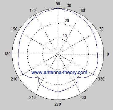
Slot antenna gain. These antennas feature omnidirectional gain around the azimuth with horizontal polarization. However the slot antenna and half-wave dipole antenna show variation according to the polarization. This half wavelength slot resembles a half-wave dipole according to radiation and gain.
When the plate is driven as an antenna by an applied radio frequency current the slot radiates electromagnetic waves in a way similar to a dipole antenna. The application of slot antennas can be versatile. The Broadband UHF TV Slot antenna provides exceptional bandwidth.
Slot antennas are usually used at. To gain an intuition about slot antennas first well learn Babinets principle put into antenna terms by H. This design specifications are chosen for high gain and mechanical robustness.
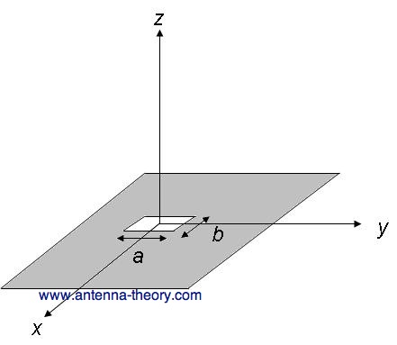
Suppose we have a rectangular conductive sheet over which a horizontal slot is cut having length λ2 and the breadth extremely less than λ2 let it be ω. The slotted waveguide antenna designed is a directional type antenna with gain of 16db. One of the ways for.
Length of the slot determines the. A slot antenna consists of a metal surface usually a flat plate with one or more holes or slots cut out. So many times it is very much required to know the gain and beam width of some standard antennas like dipole yagi antenna some specific gain.
Thus bandwidth is increases by slot on patch but it does not affect to the gain of patch. An FSS is loaded with a slot antenna for gain improvement by utilizing modified circular loop is designed in for 5G applications the slot antenna gain increment is based on microstrip feed. A Compact High Gain Multiband Bowtie Slot Antenna with Miniaturized Triangular Shaped Metallic Ground Plane Authors Zaheer A.
Then it is expanded to feed a 16 16 CP array antenna which achieves the highest gain. Current ultra-wide bandwidth UWB and high-gain antennas include mainly log-periodic antenna traditional transverse electromagnetic TEM horn antenna spiral antenna bow-tie antenna tapered slot antenna and microstrip patch antenna. Following this procedure a slot antenna is designed in the frequency band of 5-8 GHz for the purpose of gain enhancement over the entire operating band.
Slotted waveguide antennas are mostly employed in Radar applications. The feeding of the slot antenna can be done with ordinary two-wire line. Connected to one side of the slot and the outside conductor of the cable - to the other side of the slot.
Shaped slot was chosen in the ground plane with a specific angle of rotation to excite two close resonant frequencies leading to a wide bandwidth. The value of 485 Ω applies only to a feeding point at the center. Halos are normally horizontally polarized.
Additionally power handling and stable pattern performance gain only 20 of the weightwind loading of a compatible UHF panel array. In the article 5 the author describes the waveguide slot antenna array the distinguishing feature of which is the original location of the slots. Waveguide slot antennas usually with an array of slots for higher gain like Figure 7-1 are used at frequencies from 2 to 24 GHz while simple slotted-cylinder antennas like Figure 7-2.
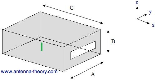
The Slot Cube The diminutive 10 x 10 x 7 inch 2-meter base-station antenna shown in Figure 1 has the omnidirectional gain of a J-pole but it is more effi-cient. Slot antennas are popular omnidirectional microwave antennas. However the traditional Yagi antenna and microstrip patch antenna have narrow bandwidth.
The impedance is dependent on the feeding point as in a dipole. Dayo College of Electronic and Information Engineering Nanjing University of Aeronautics and Astronautics Nanjing 211106 Peoples Republic of China. The feeding network of the antenna consists of two layers of 64 subarrays fed with a 2 2 cavity-backed slot antenna.
This structure has a high realized gain of 787 dB at a frequency varies from 36 GHz to 61GHz and an impedance bandwidth of 5154. Slot antennas are popular omnidirectional microwave antennas. A shift of the feed point from the center to the edge steadily decreases the impedance.
The shape and size of the slot as well as the driving frequency determine the radiation pattern. No it is not a halo - it is a folded skeleton-slot antenna. The slot antenna can be considered as a loaded version of the INF antenna.
The bandwidth is 201MHz and gain is 238dB. The INF and the slot antennas behave similarly. The dual of a slot antenna would be if the conductive material and air were interchanged - that is the slot antenna became a.
Waveguide slot antennas usually with an array of slots for higher gain like Figure 7-1 are used at frequencies from 2 to 24 GHz while simple slotted-cylinder antennas like Figure. In this paper a 4-way sequential-phase feeding network based on the RGW is proposed. Slotted Microstrip Patch Antenna.
By simulating this slotted antenna resulting in return loss of -1183dB at resonant frequency 54GHz. This antenna is vertically polarized by feeding the top and bottom loops in. These antennas feature omnidirectional gain around the azimuth with horizontal polarization.
This principle relates the radiated fields and impedance of an aperture or slot antenna to that of the field of its dual antenna. The gain of this array antenna is 159 dB. The slot length is some λ2 for the slot antenna and λ4 long for the INF antenna.
The antenna has a gain which depends principally upon its length and is typically 5 to 9 dBi. I am an antenna designing. Working of Slot Antenna.
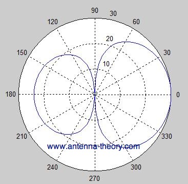
I am working on the array of slot antenna design to get high gain and single major lobe. Having manufactured Slot Antennas for over 35 years Jampro provides extensive system design field testing. On the other hand slot antennas have high gain their construction and mounting on the UAVs wings is simple and their radiation pattern is directional while their back lobes are suppressed a fact that permits use of two of them in a back to back configuration for both UAVs wings with minimum interference risks.
Slot Antenna

Slot Antenna Model Using Cst Microwave Studio Zoomed In Download Scientific Diagram

3d Gain Of A Cpw Feed Square Slot Antenna At 3 2 Ghz A Without And Download Scientific Diagram

The Radiation Pattern Of The Slot Antenna At 5 6 Ghz In The Two Cases Download Scientific Diagram

Slot Antenna Ppt Download

2 3d Radiation Pattern Of A Slotted Waveguide Antenna Download Scientific Diagram
Printed Slot Antenna On Thin Dielectric Layer Download Scientific Diagram

Enhanced Gain Planar Substrate Integrated Waveguide Cavity Backed Slot Antenna With Rectangular Slot Window On Superstrate Kang 2014 Etri Journal Wiley Online Library
Antennas Cavity Backed Slot Antennas

Comparison Of Radiation Patterns Of A Slot Antenna In A Metal Ground Download Scientific Diagram
Antennas Cavity Backed Slot Antennas

Slot Antenna An Overview Sciencedirect Topics

A Schematic Of The Tapered Slot Antenna Geometry Illustrating Full Download Scientific Diagram
Antennas Cavity Backed Slot Antennas
Posting Komentar untuk "Slot Antenna Gain"